
MYRTUS Design and Programming Environment
The three MYRTUS technology pillars
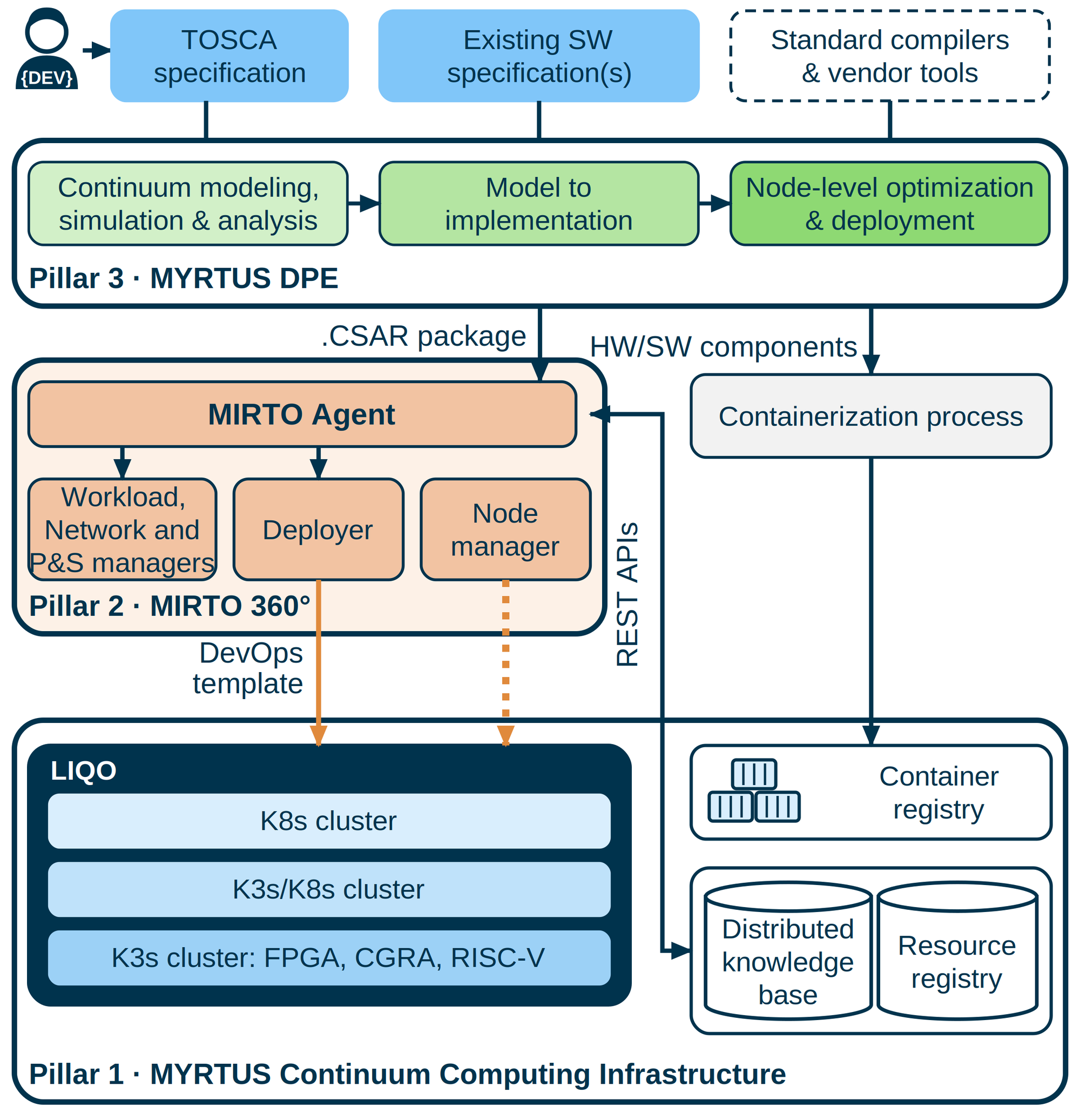
MYRTUS technology results are organised around three pillars that together form a chain from application design to execution. Pillar 1 provides the edge-fog-cloud reference infrastructure on which applications run. Pillar 2 provides MIRTO, the cognitive engine that orchestrates workloads across this infrastructure, deciding where and how each workload is placed and executed. Pillar 3 provides the Design and Programming Environment (DPE), the methodology and toolchain through which applications are developed, optimised and packaged for deployment.
See how the three pillars work together in Concept and Methodologies →
MYRTUS Pillar 3
The MYRTUS DPE is responsible for creating the deployment specification for the continuum, including all the executables and configuration files to program the heterogeneous components. Moreover, it exports meta-information with non-functional properties of the applications to aid the MIRTO Cognitive Engine in runtime decision-making. As shown in Figure 1, the DPE is composed of three steps: 1) a step for high-level modelling, simulation, and analysis; 2) a step for turning the model into a concrete implementation; and 3) a step on node-level optimisation and deployment of key computational kernels of the application. The tools are integrated through standard interfaces and exchange formats, with TOSCA as the common description of the application and MLIR as the common infrastructure of the compiler, so that an application modelled in Step 1 can be carried down to executables for heterogeneous targets. A minimal end-to-end flow, inspired by the MYRTUS use cases, shows how the tools of the three steps work together.
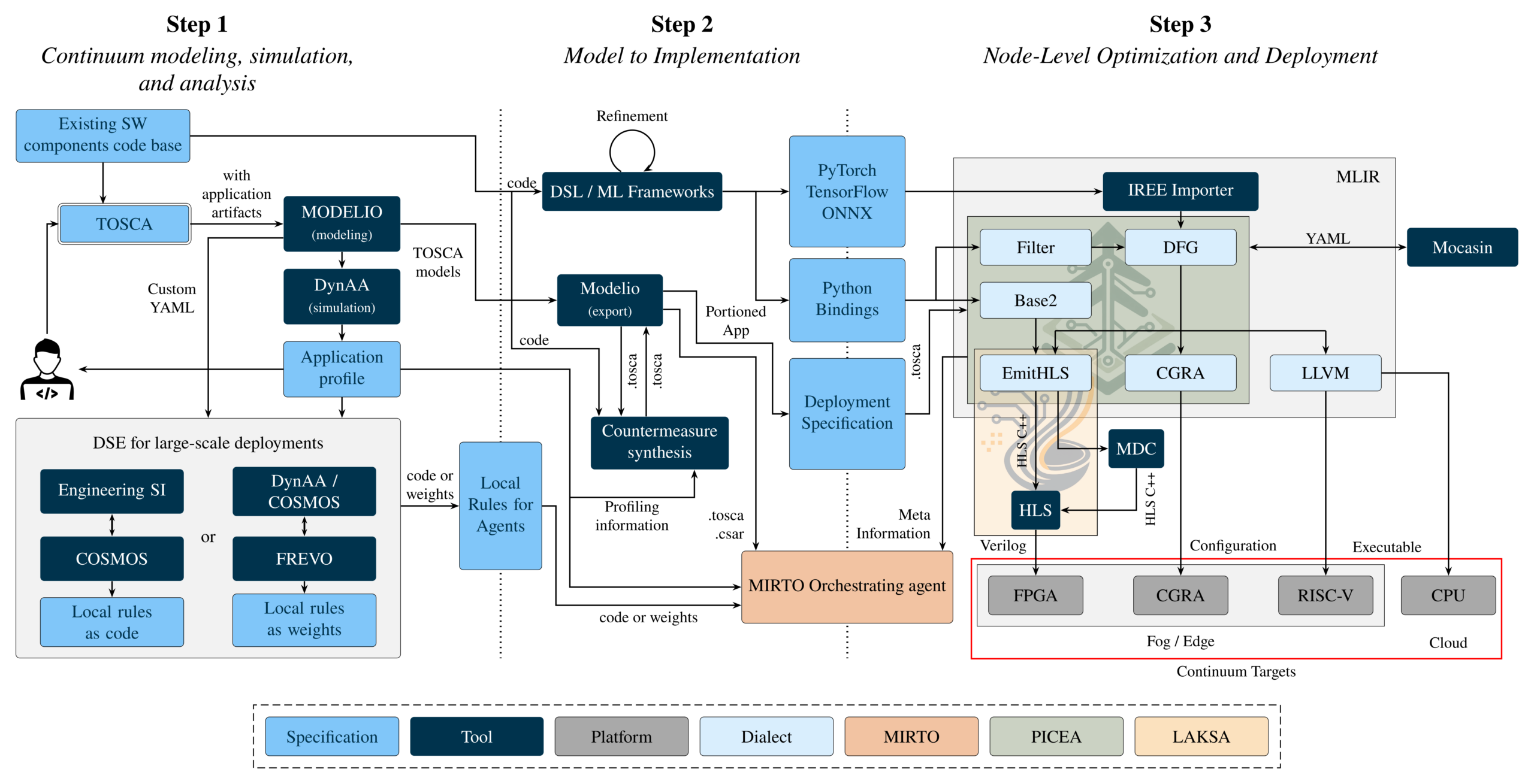
The MYRTUS DPE is responsible for creating the deployment specification for the continuum, including all the executables and configuration files to program the heterogeneous components. Moreover, it exports meta-information with non-functional properties of the applications to aid the MIRTO Cognitive Engine in runtime decision-making. As shown in Figure 1, the DPE is composed of three steps: 1) a step for high-level modelling, simulation, and analysis; 2) a step for turning the model into a concrete implementation; and 3) a step on node-level optimisation and deployment of key computational kernels of the application. The steps are connected through standard exchange formats, TOSCA between the tools and MLIR inside the compiler, so that an application modelled in Step 1 can be carried down to executables for heterogeneous targets. This end-to-end flow has been demonstrated on examples taken from the MYRTUS use cases.
Step 1 – Continuum modeling, simulation and analysis
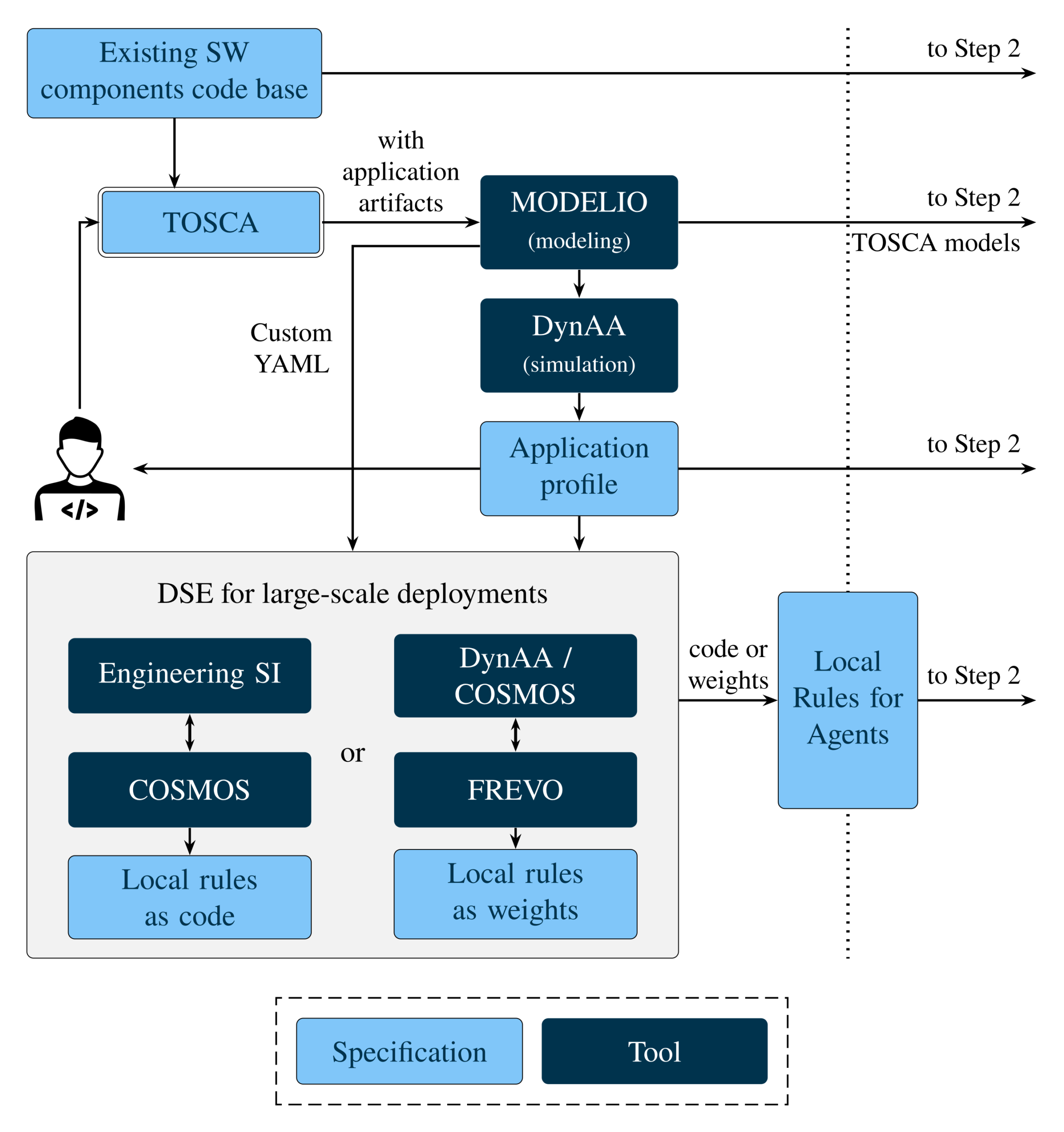
Step 1 takes an application that is still at the level of requirements and existing software components and turns it into a model of its deployment across the edge-fog-cloud continuum, which can be simulated, tuned and handed over to Step 2. This step produces three outputs: the TOSCA models of the application, an application profile obtained through simulation, and the local rules for agents that guide workload placement at runtime.
Modelling. Modelio TOSCA Designer, an extension of the Modelio modelling platform, is the tool through which the TOSCA model is created. Application developers and system architects use it to describe the topology of the application, the relationships between software components and computing nodes, and the policies and constraints of the application, such as the expected end-to-end latency. The model also carries properties used by the next steps, such as the sensitivity and integrity of the data handled by each component, from which Step 2 synthesises security countermeasures. TOSCA Designer exports the model as Cloud Service Archive (.csar) packages and .tosca files, which can be used by any TOSCA-compliant orchestrator, including MIRTO, and has been publicly released.
Simulation. DynAA, a discrete-event simulation framework, simulates the modelled topology and produces an application profile with estimates of resource utilisation, latency and power consumption. Developers use it to spot bottlenecks and refine the model before deployment. Within MYRTUS, DynAA has been extended with models of continuum infrastructures (computing nodes, memory, networks and software components) through the NexusSim framework, and both have been released as open source.
Design space exploration for large-scale deployments. When an application runs on many nodes, deciding where each component should be placed cannot be done by hand. In MYRTUS, placement at runtime relies on swarm intelligence: the MIRTO agents follow local rules, and good placements emerge from their interaction. This block produces those local rules, starting from the TOSCA model, which TOSCA Designer also exports as a dedicated YAML file, and from the application profile. Two alternative paths are available, and one of them is used for a given deployment.
Engineering SI: local rules as code. When the placement behaviour is already known, it is engineered explicitly, using a known swarm-intelligence algorithm such as ant colony optimisation or an artificial hormone algorithm. COSMOS, a simulation framework developed in MYRTUS, simulates agents and workloads on edge-fog-cloud topologies to evaluate the algorithm. The result is a set of local rules written as code: explicit and interpretable logic that the agents execute.
FREVO: local rules as weights. When the right behaviour is not known in advance, it is discovered through simulated experience. FREVO evolves a controller, typically an evolutionary fuzzy controller, over many simulated generations, using COSMOS to evaluate how well each candidate places the workload. The result is a set of learned parameters, the weights of the controller, rather than a procedure written by hand.
In both cases, the local rules are exported together with the TOSCA models and the application profile, and are then passed on to the MIRTO agents for runtime workload placement.
Step 2- Model to implementation
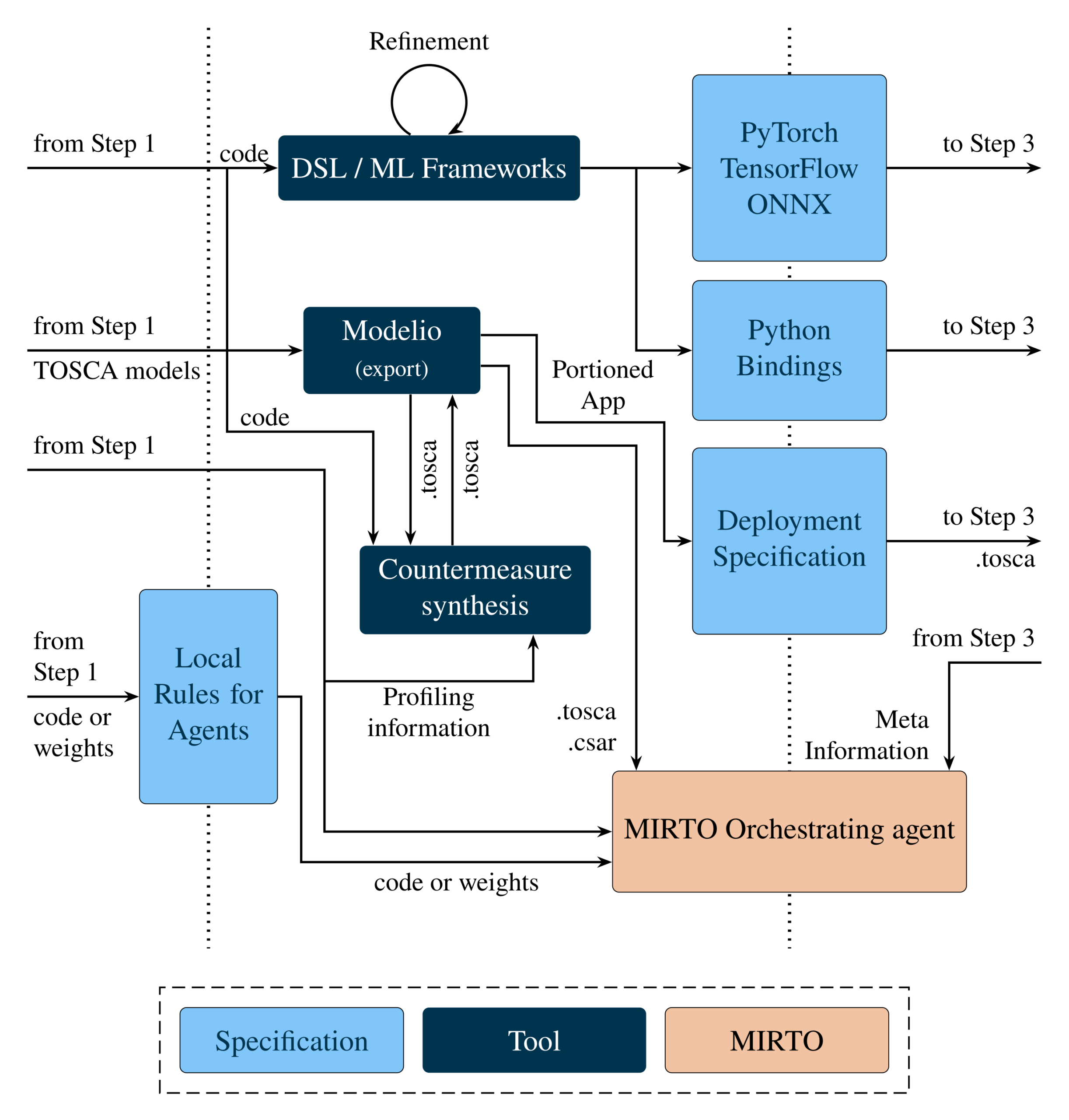
Step 2 turns the model of the application into a concrete implementation. It receives from Step 1 the TOSCA models, the application profile and the existing software components, and produces what the next stages need: the code of the key kernels to be optimised in Step 3, the deployment specification in TOSCA format, and the security countermeasures to be deployed with the application. The local rules for agents produced in Step 1 are passed on to MIRTO.
From model to code. Modelio exports the parts of the application that need acceleration (the “portioned app”, such as signal-processing kernels or machine learning components) and the deployment specification, which tells Step 3 which components are to be compiled and is also provided to MIRTO as .tosca/.csar files. The code of these components comes from machine learning frameworks (PyTorch, TensorFlow, ONNX) or, for signal-processing kernels such as filters, from a small domain-specific language exposed through Python bindings, which is closer to the way domain experts already work than low-level C/C++. Before compilation, models can go through refinement steps in their own framework, for example quantisation-aware training to fit resource-constrained FPGA devices.
Threat modelling. Security is addressed from the design stage. Modelio Attack-Defence Tree (ADT) Designer lets system architects model how the application could be attacked, as a tree of attack steps, and attach to each threat the countermeasures that mitigate it. Its integration with TOSCA Designer keeps security considerations tied to the topology of the application.
Countermeasure synthesis. The Countermeasure Synthesizer, developed from scratch in MYRTUS, turns security requests into concrete implementations. It reads from the TOSCA model the countermeasures requested in the ADT or, more automatically, the sensitivity and integrity of the data handled by each component, together with the throughput and energy levels of the computing nodes. From these it derives the required security level for four functionalities (encryption, key encapsulation, hashing and digital signatures) and selects from a library of cryptographic primitives the implementations that meet that level with the best trade-off between energy and throughput, based on profiling information. The result is written back into the TOSCA model. Existing approaches to automatic protection work at a lower level, hardening a single software routine or hardware circuit; the Countermeasure Synthesizer instead starts from the model of the whole application and packages the selected countermeasures as containers suited to the computing continuum.
At runtime, the selected primitives are executed by Privacy and Security (P&S) containers attached to the application components, either prepared in advance or built from source code supplied by the developer. Because several primitives are made available in each container, MIRTO can switch between them at runtime when conditions change. When the profiling information for the target node is not available at design time, the security requirements are written into the TOSCA model and the same selection is made at runtime, once the primitives have been profiled on the actual node.
Catalogue of tools involved in the Step 2
Step 3 – Node-level optimisation and deployment
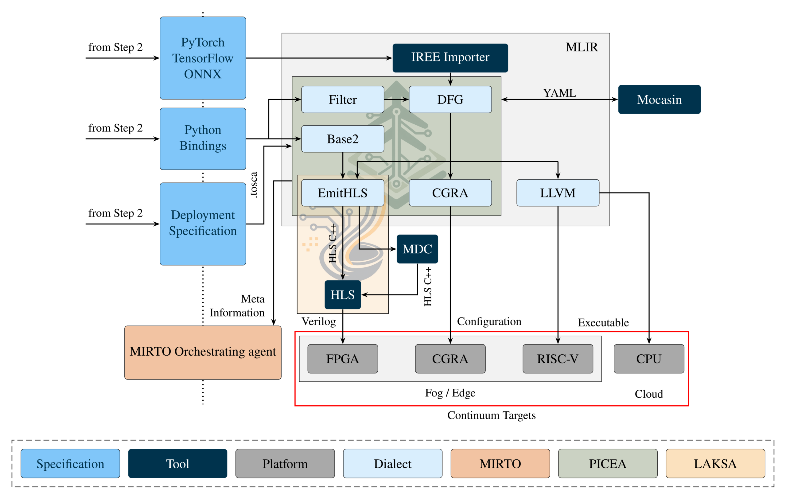
This step results in the executables and bitstreams for running and/or configuring the different computing components. PICEA, a common interoperability framework built on MLIR that extends the work started in the EVEREST project, allows i) importing third-party codes (from DSLs or ML models), ii) having access to third-party tools, and iii) compiling code for different targets (such as reconfigurable accelerators, CPUs, or customizable RISC-V cores). From a single input, it can generate several implementation variants for different targets, which are provided to the MIRTO Cognitive Engine so that it can choose at runtime which one to deploy.
Applications enter PICEA either as ML models, which are imported into linalg through the IREE importer, or as signal-processing kernels described through a Python front end, where the filter dialect describes each filter by what it computes rather than how, and the base2 dialect provides the custom fixed-point data types. From there the dfg dialect models the application as a dataflow graph, and the individual target paths branch off: emithls generates HLS C++ for the FPGA path, either through LAKSA, which automatically optimises the design for the available FPGA resources and produces the IP with Vitis HLS, or through MDC, which turns the Vitis HLS output into runtime-reconfigurable accelerators; the cgra dialect selects the loops to offload to the CGRA and maps them to its configurations, while the control code runs on the coupled RISC-V core; and the llvm dialect covers CPU and RISC-V.
Mocasin, a high-level Python-based DSE tool for heterogeneous many-cores, has been extended with models of the MYRTUS target nodes (the Kria KV260 board, with Arm cores and an FPGA, and the RISC-V+CGRA edge node). PICEA exports the dataflow graph of the application to Mocasin as a YAML description, and Mocasin explores how to map it onto the target node, deriving Pareto-optimal operating points (e.g., trade-offs between execution time and energy).
The deployment specification is passed from Modelio to PICEA in TOSCA format (i.e., YAML) and indicates which components of the application are compiled in this step. The rest of the application is compiled with standard compilers, ensuring it can interoperate with the accelerated portions.